An Overview of the 4-20 mA Current Loop

In this advanced world of process control, there is a wide array of process inputs. One of the most predominant types of input in industries requiring process control today is analog signals – information about the process is transmitted through varying amounts of voltage or current. When compared to all the analog signals that are used for transmitting process information, the 4-20 mA is considered to have set a dominant standard in the industry. Let’s take a deeper look at how it came to be, how it works, and how you can take advantage of this process control techniques for your projects on the microcontroller.
Everything you need to know about the basics of 4-20 mA
Sensors or other devices with a 4-20 mA current loop out are exceedingly common in industrial measurement and control applications. This is because they are easy to deploy, generate a low noise output, have a wider power supply requirements, and can be transmitted without loss over great distances. In fact, pneumatic signalling system was more predominantly used before the advent of electric controls. These signaling systems not only provided power to move actuators but also the ability to sense conditions.
Though pneumatic systems are still used by industries where things tend to go boom around electricity, in the 1940s and 1950s, 4-20 mA current loop systems set a standard which helped in monitoring temperature, pressure, and flow etc. The idea behind 4-20 mA current loop operation is that the sensor draws current from its power source which is directly proportional to the mechanical property it measures. For instance, if a 100 psi sensor with the current loop output is applied with 0 psi, it is revealed that the sensor draws 4 mA from its power source. If the bottom value of the loop current had been set to zero, detecting the difference between a broken loop wire with the legitimate lower limit on a sensor becomes impossible. In addition, it must be observed that the relationship of mechanical property measurement to current output is almost always linear.
Additionally, current loops control a wide range of actuators – from valves to motor drivers – thus proving that 4-20 mA is not just limited to sensors.
The 4-20 mA in your latest Arduino project
Have you ever wondered how to incorporate a 4-20 mA device into your latest Arduino project? Remember, loop operation is straightforward: a sensor output voltage is first converted to a proportional current. The 4-20 mA current back is then converted into a voltage by the receiver at the remote end which can be further processed by a display module or computer.
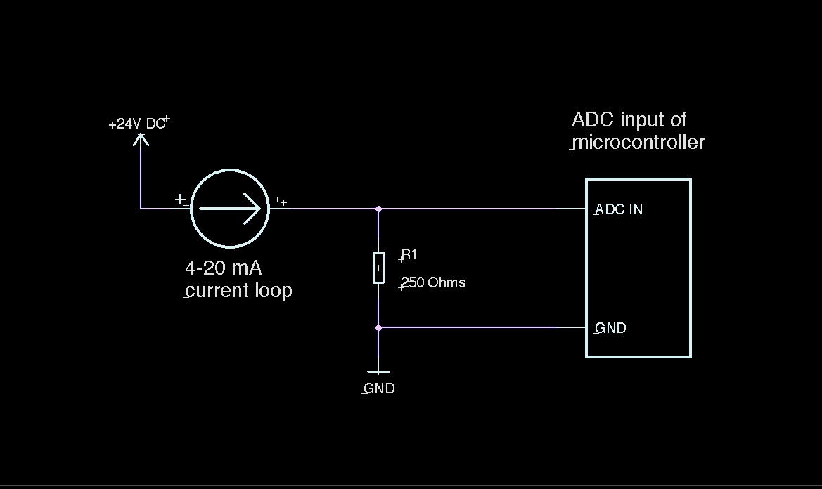
To find the value of the resistor to use to sample the signal from a 4-20 mA sensor with a 5V powered microcontroller, simply use Ohm's Law:
- U = R * I (U in Volts, R in Ohms and I in Amperes)
- 5 = R * 0,020
- R = 5 / 0,020 = 250 Ohms
All you need to do is to place a 250 Ohms resistor in parallel at the input of the ADC of the microcontroller, as in the following schema:

Hope this will open you new doors to sensors interfacing!

